Connecting BAT2 scales into the RS485 network
This tutorial will show you how to connect BAT2 scales into the RS-485 network.
Contents
Powering each scale separately
USB converters with termination resistor
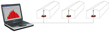
Operating the scales from the office
The basics
RS485 is a wired network used for transmitting data over long distances exceeding 1000 meters. There can be up to 31 scales connected to the RS485 network and all of them can communicate with a master PC, PLC or other equipment. All scales in the network can be fully operated from the office.
The RS485 uses three signals for communication: A, B and GND. You can read more about the RS485 standard on Wikipedia or on Maxim website.
Scale connection
The scale is connected to the RS485 network using a male connector located on the bottom of the box:
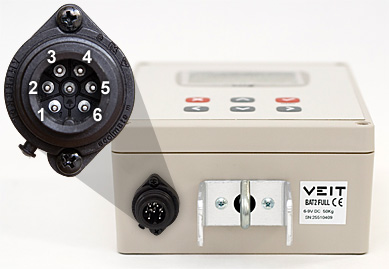
Wiring scheme of the connector is shown in the following table:
| Pin | Meaning |
| 1 | +24 V: POWER |
| 2 | A: RS485 |
| 3 | B: RS485 |
| 4 | 0 V: POWER |
| 5 | CGND: common GND |
| 6 | SHD: shielding |
Note: different manufacturers use opposite meaning of signals A and B. If the communication doesn’t work after installation and you don’t know what could be wrong, try to swap the A and B wires in the connector.
PC connection
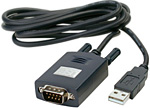
Scales in the RS485 network are usually connected to a PC in the office, which is used to operate the scales. Common computers don’t have any RS485 port, so a USB to RS485 converter needs to be used. The converter is placed between the PC and the RS485 network.
You can choose from many converters available on the market.
Cable
The cable between the PC and the scales has major influence on the connection quality. On shorter distances, any shielded cable can be used. On longer distances, shielded twisted-pair is recommended.
Connecting all together
Now we know what is needed, so let’s connect it all together and build a simple RS485 network with 3 scales:
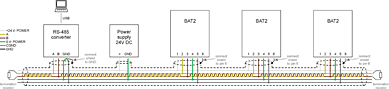
The basic idea is that the whole network has only two ends, creating a so called linear topology. The cable runs from the RS485 converter to the power supply and then to the first scale, second scale and last third scale. Star networks will work on short distances, but generally should be avoided. If you need to use the star network on longer distances, try to use an RS-485 converter with more ports, so each network section will use its own port.
The RS485 converter uses signals A, B and GND for the communication. The converter is the primary source of signal in the network, so the shield (SHD) and power ground (0 V: POWER) wires are connected to the GND pin of the converter.
All scales in the network are powered via the cable from one central power supply. For example common Ethernet cable can be easily purchased and contains 8 wires (4 twisted pairs). We need only 3 wires for communication, so remaining 5 wires can be used for power supply of all scales. Always use as many wires as possible for powering to avoid voltage drop.
The scales are connected to the network via a female connector. Don’t forget to connect the cable shielding to pin 6 in the connector.
Termination resistors
In large networks, termination resistors should be installed between wires A and B, on both physical ends of the cable:
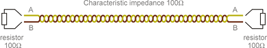
The termination resistors prevent the signal to be reflected back from the end, causing interference. Value of the termination resistor should be equal to the characteristic impedance of the cable. It is usually printed on the cable itself; the Ethernet cable needs 100Ω resistors.
In small networks, the termination resistors can be omitted, but the communication errors must be tested after installation.
Powering each scale separately
If you use a thin cable without any free wires available for central power supply, each scale can be powered separately using an AC/DC adaptor:
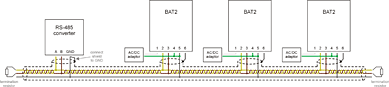
Make sure you interconnect pins 4 and 5 (signals 0 V:POWER and CGND) in the connector of all scales.
USB converters with termination resistor
USB to RS485 converters usually contain an internal termination resistor, so you need an external resistor only on the second end of the cable:
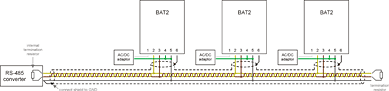
The internal resistor can be enabled or disabled in the converter, usually via jumpers or DIP switches. Read the instructions of your converter how to enable it.
Termination resistor on the other end of the cable still should be installed externally.
Configuring the scales
All scales in the network must be configured to use same communication parameters (baud rate, parity, protocol type, etc.). The same parameters must also be set in the PC software. In other words, all units in the network must "talk the same language".
The scales use the MODBUS communication protocol and both RTU and ASCII modes are supported. We recommend using the RTU mode, which transfers less data in comparison with the ASCII mode. The ASCII mode is useful when the scales are connected indirectly, via a modem, GSM or other equipment.
Additionally, each scale connected to the network must have a unique network address:
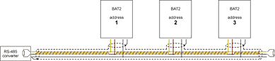
There cannot be two scales with the same address in the network.
Operating the scales from the office
When everything is connected together, we can start monitoring and operating the scales from the PC. Standard BAT2 software will be used, so you don’t need anything extra.
Start the BAT2 application and select menu Scale – RS485 scales. New window with all installed scales is shown:
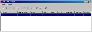
We haven’t defined any scales so far, so the table is empty. To define the scales connected in the network, select menu Options – Add/remove scales. For each scale, enter its address, COM port of the USB converter and the scale name. After all 3 scales are defined the window should look like this:
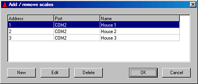
Click OK. The program will start to monitor all scales over the RS485 network, showing the current state of each scale in the table:
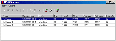
All scales can be fully operated in menu Scale, so you can easily start weighing or configure the scale from your office.
If you want to download all data from a scale, select the scale in the table and go to menu Scale – Download results. All data from the scale will be read and the results will be saved the same way as when using the memory module.
Checking communication errors
After successful installation, communication quality should be checked. Open the window with current state of all scales and stay there for a while. The program is periodically reading data from all scales and the error rate is automatically calculated.
Select menu Options – Communication errors to check the error rate for each scale separately:
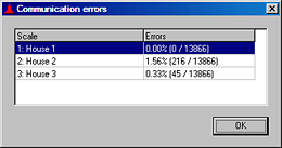
If the error rate of any scale is too high, check the cable installation and parameters in the scale.
If the error rate is too high for all scales, try to decrease the communication speed. Slower communication is more resistant against interference and can work even with poor cable installation.